Easy Tesla Coil

Wireless electricity is here! From wirelessly powered lighting to wireless chargers and even wireless smart homes, wireless transmission of power is an emerging technology with innumerable applications.
A light bulb powered with no wires? A cell phone charger that doesn’t need to be plugged in? A home with no plugs, no wires and everything just ‘works’? It’s not magic, it’s no mystery, it’s science!
The invention of wireless power transmission is typically attributed to 20th century inventor Nikola Tesla, though the technology may have been in use much earlier. Since then, however, improved designs and modern components make this an easy DIY project anyone can do with just a few simple parts!
Let’s get started!
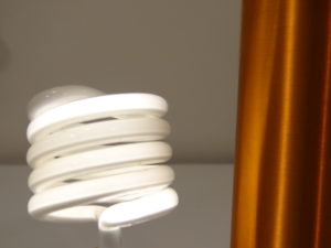
FUN FACT: A Tesla Coil can even create mini lightning bolts that spark from the surface!
CAUTION: Do not use near persons with pacemakers, sensitive electronics or flammable materials.
Here’s how it works
Electricity needs to travel through wires, right? Well, not anymore!
This simple device shows how electricity can be transmitted wirelessly to power all types of electrical devices for convenience, necessity or just plain awesomeness!
Here’s how it works. We are creating a system that converts a low voltage to a high voltage and simultaneously turns itself on and off very quickly. That’s all it takes to transmit wireless electricity. A few volts of electricity are passed to one side of a coil of wire and to a grounded capacitor connected to the negative side of the power supply. The other side of the coil is connected to the collector of a transistor, a device that can turn off the flow of current based on an input signal, and then to ground as well. This causes two things to happen. The capacitor begins to charge while the coil (based on this) begins to radiate an electromagnetic field. This coil is then placed around a second coil with many more windings of a smaller gauge wire which creates a transformer, converting a low input voltage to a very high voltage in the second coil. This secondary coil is then connected to both a resistor connected to the power source and the base of the transistor which then shuts off the flow of current to the first primary coil.
This circuit configuration creates a feedback loop which automatically turns on and off the secondary coil hundreds of times per second which creates a high voltage, high frequency electric field capable of transmitting wireless electricity!
Simple enough, right?
FUN FACT: A transistor is what makes the processors in computers work, so, in essence, we are building a super simple computer to control our Tesla Coil!
What you’ll need

The coolest thing about this project is its simplicity! This is the world’s simplest and easiest Tesla Coil circuit design! With just a few simple parts you’ll be creating your own mini lightning bolts and powering things wirelessly in no time!
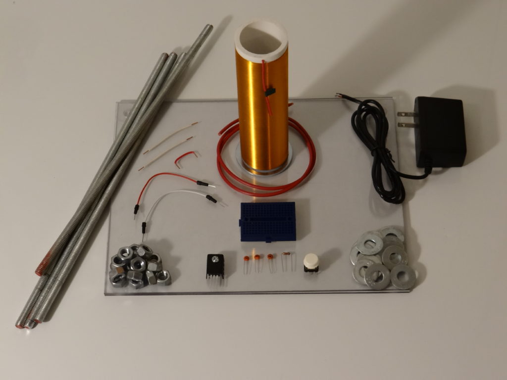
Here are the parts you’ll need:
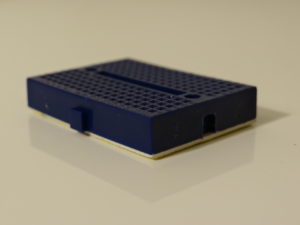
(1) Breadboard Circuit (A-J/1-17)
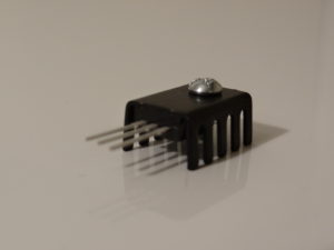
(1) MJE3055T Transistor with Heat Sink
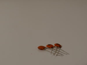
(3) 104 .1uF Ceramic Capacitors
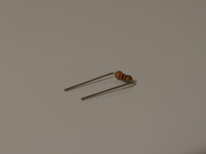
(1) 1K Resistor
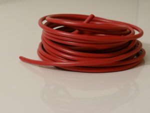
(1) Solid Core 16 ga. Insulated Copper Wire, ~1.5ft.
(1) PVC Pipe 2″ x 2.5″ diam.
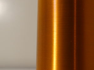
(1) AWG 27 Insulated Magnet Wire
(1) PVC Pipe 7″ x 2″ diam.
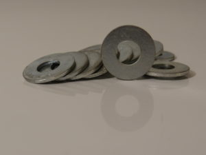
(1) 3″ Steel Washer
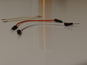
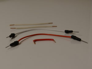
(5) Jumper Wires
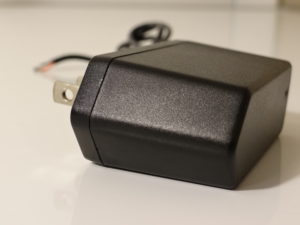
(1) 12v/1A Power Supply
(2) 8″ x 10″ Plexiglass Sheets
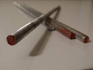
(4) 5/15″ Threaded Rod
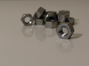
(16) 5/16″ Nuts
(16) 5/16″ Washers
(8) 5/16″ Rubber End Caps
Also, get the circuit diagram here.
FUN FACT: Tesla used a high voltage spark gap to control his circuit; we’ll be using something a bit more modern and reliable, an MJE3055T transistor.
Wind your coils
To begin, we’ll need to wind out coils. To do this, we’ll need to be precise and accurate otherwise our coils won’t function properly.
Get pre-wound coils and full parts kit here
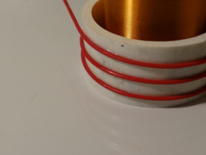
First, we will make our primary coil. We will wrap our short 2.5″ PVC pipe with the 16 ga. Insulated Copper Wire making three rotations evenly spaced about 1/4″ apart and secure with tape. Then strip the ends.
Next, we will take our 2″ PVC and line up the magnet wire across about 1/4″ from the bottom and secure it with tape leaving several inches extra on the end. Now comes the tedious part so get comfortable. We will now wrap the magnet wire around several hundred times until we reach around 1/4″ from the top. Be sure to wrap tightly, straight and without gaps between windings. Also, be sure to add a piece of tape every inch or so to keep everything secure. Once you reach the top, leave a couple inches of additional wire, cut and strip both ends by lightly sanding the ends of the wire. Then you can secure your winding by wrapping with tape from top to bottom. Lastly, press the stripped wire end between the top of the PVC and your 3″ washer and secure with glue. This will act as your secondary coil and transmitter cap.
Build your circuit
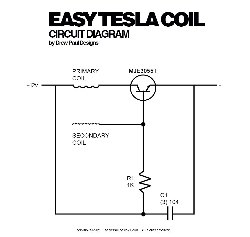

There are only a few parts, so building your circuit is simple. Just make sure to have the circuit diagram handy while following along.
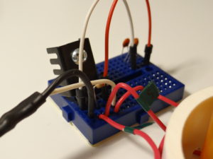
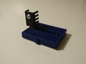
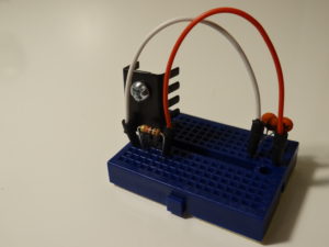
First we will install the three legs of the Transistor in breadboard slots E1, E2 and E3 with the heat sink and front of the transistor facing back toward slot F.
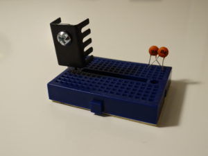
Next we will insert the three capacitors into slots H14/H17, I14/I17 and J14/J17 respectively so that they are in parallel.
Now, lets connect the first leg of the transistor to one side of our capacitors with a jumper wire. Connect one end of a jumper wire to slot D1 and the other to F14.
Next, we’ll connect a jumper wire from the other side of our capacitors back to where our ground will be. Connect one end of a jumper wire to slot F17 and the other end to slot D5.
Insert one end of your resister on the same column, slot C5, and the connect the other end of the resistor to the base of the transistor by inserting it in slot C3.
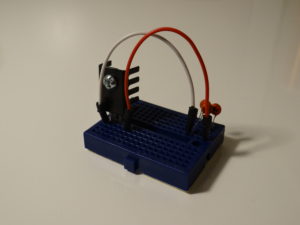
Next, connect one last jumper wire to slot A5 and the other end to slot B11. This will allow us to connect to our primary coil.
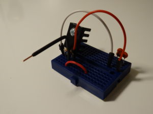
We will now insert our secondary coil into our primary coil keeping it centered.
The bottom wire of your primary coil can be inserted into slot A11. The top wire from your primary can be connected to slot A2. Connect your secondary coil by inserting the bottom wire into slot A3, and the base of your transistor.
Check all connections before proceeding.
Lastly, connect the positive from your power supply (+) to slot B5, and connect the negative from your power supply (-) to slot B1.
You may now carefully test your circuit by plugging it in momentarily.
NOTE: To avoid overheating, only power your Tesla Coil for short durations of no more than 20 seconds or less.
Construct the enclosure
Now we will build an enclosure to display our Tesla Coil. This enclosure is also important in order to isolate the coil from flammable materials and sensitive electronics as well as to keep the coil upright and to provide a platform for experimentation.
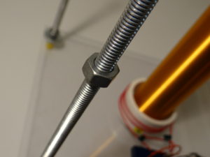
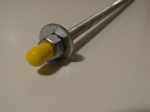
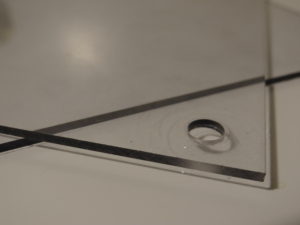
First we will place a washer, nut and end cap on each of our threaded rods. Then we can drill a 5/16″ hole in each corner of our plexiglass sheets.
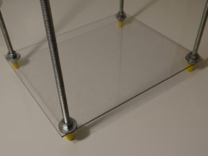
Then insert the four rods into the holes in one of your plexiglass sheets and add a washer and nut to secure, creating the base of the enclosure.
Next, place your circuit and coil on top of the sheet, making sure it is centered, and remove the adhesive backing from the breadboard in order to affix it to the platform.
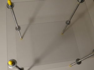
Lastly, add a nut and washer to each of the rods, place the second plexiglass sheet on top and adjust in order to tightly hold the coil in place. Once secure, add an additional washer and nut to each rod, tighten and add an end cap to each.
Your enclosure is now complete and your Tesla Coil is now ready to use!
Experiment, observation and operation

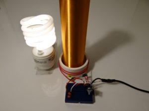
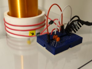
Now that your Tesla Coil is complete you can begin your experimentation.
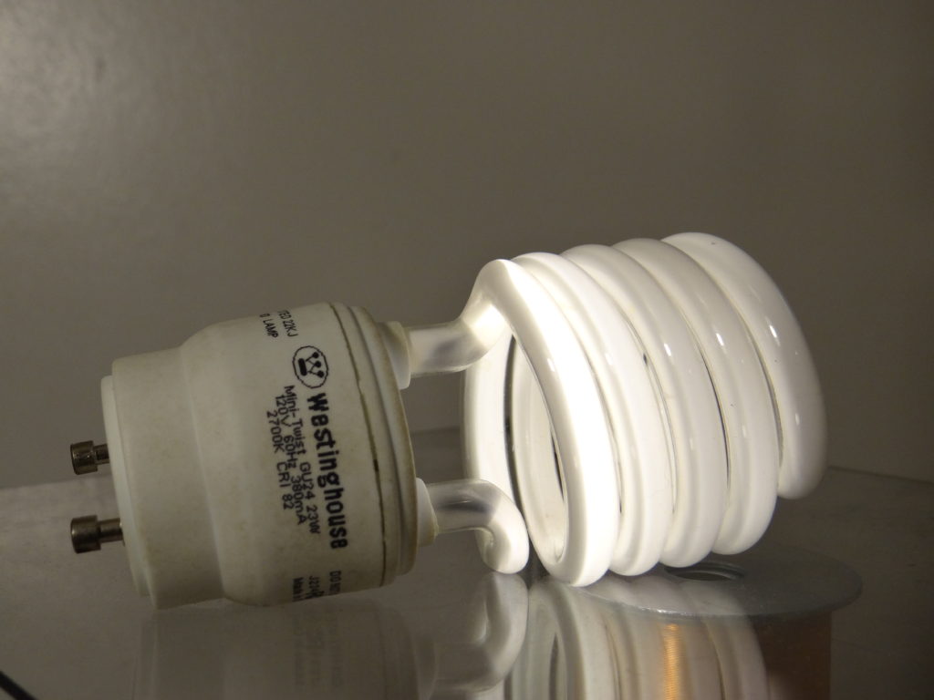
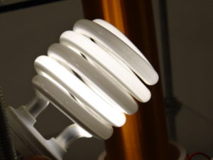
You can now connect the power and watch as florescent bulbs light up like magic once placed near the coil. Watch as sparks fly when metallic objects are place near the coil (take caution) or use a digital multi-meter to observe the high voltage field at varied distances from your coil.You can even tune your coil by lifting or lowering the primary coil to see the effects of different positioning.
Want to take it a step further? Add a resistor to an LED to to create your own wirelessly powered light bulb. You can even experiment with wireless charging coils to create your own wireless charger for mobile devices. The possibilities are endless!
What real world applications does this technology have? How can this technology be used in the future? What will you do with your Easy Tesla Coil?
Give this project a try and let us know how yours comes out by posting pictures, comments and questions in the comment section below!
googles at 10:18 am, March 29, 2019 -
hi this is very interesting
Comments are closed.